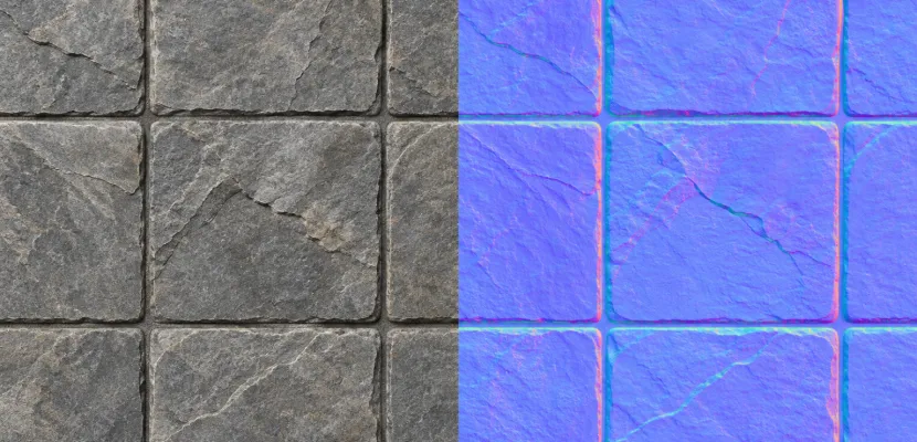
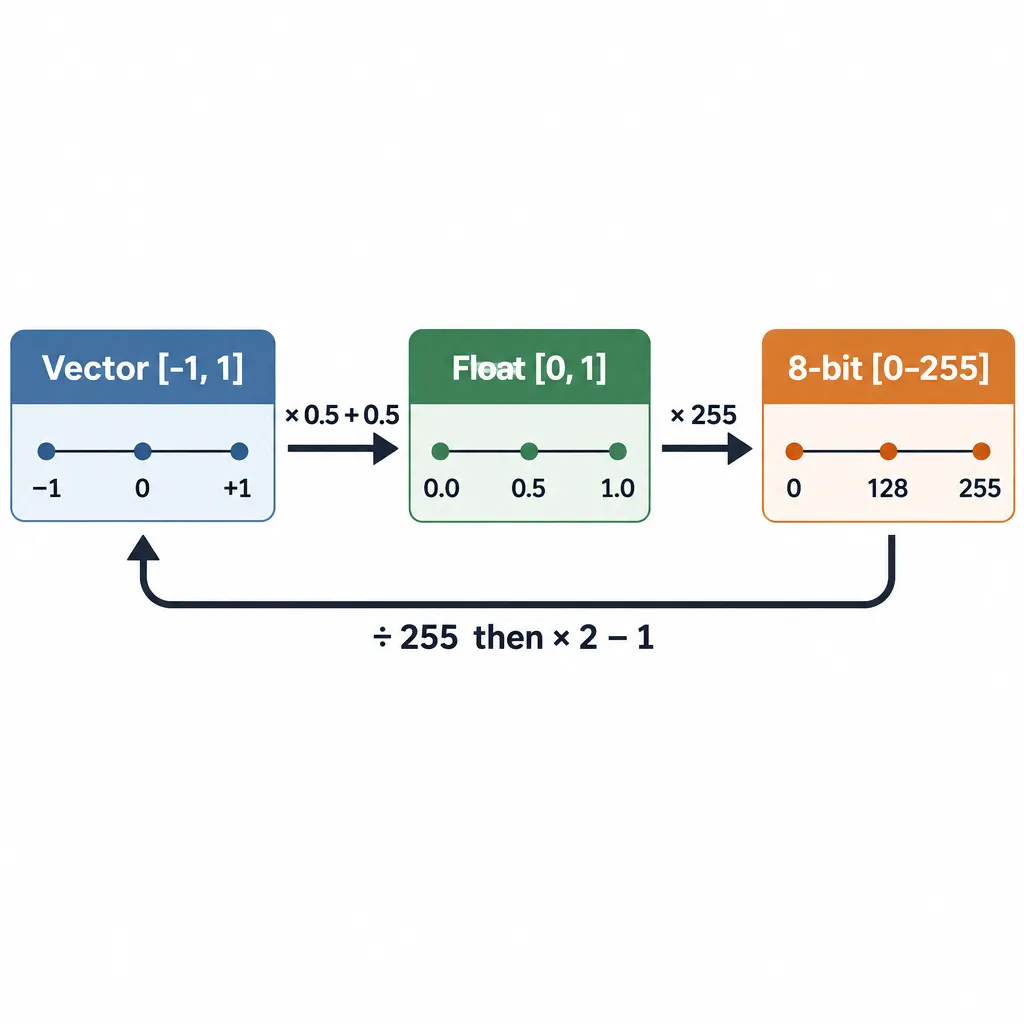
A flat tangent-space normal is conventionally stored as roughly 128, 128, 255, which is a handy example of the encoding. Each normal is a unit vector with components between -1 and 1. The texture stores it as n * 0.5 + 0.5, so the range becomes 0 to 1 in floats or 0 to 255 in 8-bit RGB, and the shader reverses it with rgb * 2.0 - 1.0.
Key takeaways
- Normal vector components live in [-1, 1]. Textures store them in [0, 1], or 0 to 255 at 8 bits.
- Encode with n * 0.5 + 0.5 and decode with rgb * 2.0 – 1.0. A flat surface is (0.5, 0.5, 1.0), or 128, 128, 255.
- In tangent space, most normals point outward, so blue usually sits between 128 and 255. That is why these maps look lilac blue. Normals with negative Z would encode below 128.
- The green channel flips between OpenGL (Y+) and DirectX (Y-) maps. Normal maps must also be read as linear data, never as sRGB.
- Two-channel formats like BC5 drop blue entirely, and the shader rebuilds Z from X and Y.
Heads up
If you searched “normal MAP range” for blood pressure: mean arterial pressure is a medical measure, and Healthline notes that doctors usually treat 70 to 100 mmHg as normal. This page covers the graphics texture. Ask a clinician about your own readings.
Fact-checked
We checked these key facts against the sources named, on November 12, 2026:
- Normalise: (0.553, -0.286, 0.782) (source: learnopengl.com)
- Each 8-bit step covers 2 ÷ 255 ≈ 0.0078 of the vector range (source: learn.microsoft.com)
- Either value decodes to within about 0.004 of zero on X and Y (source: docs.unity3d.com)
- Multiply by 2 and subtract 1: X = 0.569, Y = -0.294, Z = 0.804 (source: learnopengl.com)
- A value of 128 decodes to 128 ÷ 255 × 2 − 1 ≈ +0.0039, and 127 decodes to about −0.0039 (source: learnopengl.com)
Normal map value range: the short answer
A normal map stores a direction for every pixel. The direction is a unit vector (X, Y, Z), so each component falls between -1 and 1. Image formats can’t hold negative values in ordinary unsigned channels, so the range is shifted and halved into 0 to 1. The table below shows the same range at each stage of the pipeline.
| Channel | Vector component | Range in the vector | Float texture value | 8-bit value |
|---|---|---|---|---|
| Red | X (tangent, “right”) | -1 to 1 | 0.0 to 1.0 | 0 to 255 |
| Green | Y (bitangent, “up” in OpenGL) | -1 to 1 | 0.0 to 1.0 | 0 to 255 |
| Blue | Z (out of the surface) | -1 to 1, usually positive in tangent space | 0.0 to 1.0, usually 0.5 to 1.0 | 0 to 255, usually 128 to 255 |
The blue row is the one people usually miss. In a tangent-space map, Z is measured along the surface’s own normal, and most details face outward. That makes Z positive in most maps, so blue usually stays above 128, though a normal with negative Z would encode below 128. If a tangent-space map shows dark blue or black patches, something upstream may have gone wrong. A bake error or a broken conversion are the usual causes.
Reference normal map values
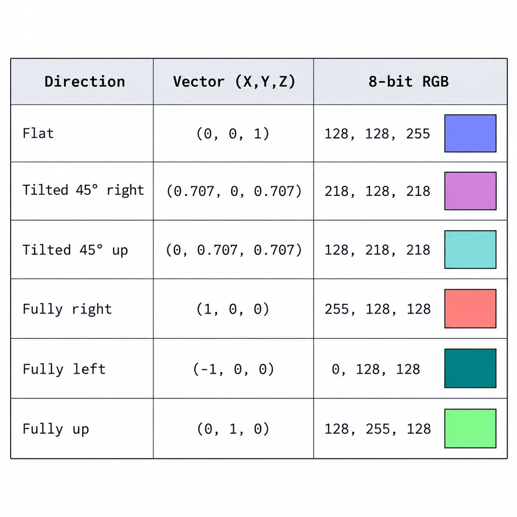
These are the values worth knowing by heart. They use the OpenGL convention (green means up), and the 8-bit numbers are rounded.
| Direction of the normal | Vector (X, Y, Z) | Float RGB | 8-bit RGB |
|---|---|---|---|
| Flat, straight out | (0, 0, 1) | (0.5, 0.5, 1.0) | 128, 128, 255 |
| Tilted 45° right | (0.707, 0, 0.707) | (0.854, 0.5, 0.854) | 218, 128, 218 |
| Tilted 45° up | (0, 0.707, 0.707) | (0.5, 0.854, 0.854) | 128, 218, 218 |
| Fully right (90°) | (1, 0, 0) | (1.0, 0.5, 0.5) | 255, 128, 128 |
| Fully left (90°) | (-1, 0, 0) | (0.0, 0.5, 0.5) | 0, 128, 128 |
| Fully up (90°) | (0, 1, 0) | (0.5, 1.0, 0.5) | 128, 255, 128 |
Real bakes rarely come near the 90° rows. Most pixels in a typical texture sit within a few dozen values of 128, 128, 255, which is why the map reads as a soft lavender with pink and green edges.
How the encoding works
The encoding is an affine remap: multiply by 0.5, then add 0.5. That maps -1 to 0, 0 to 0.5 and 1 to 1. Decoding runs the same steps in reverse.
Encode: n * 0.5 + 0.5
A baker or a generator script writes normals out like this. Here it is in plain JavaScript, the kind you would run inside a p5.js sketch:
// Turn a unit normal {x, y, z} in [-1, 1] into 8-bit RGB in [0, 255]
function encodeNormal(n) {
  return [
    Math.round((n.x * 0.5 + 0.5) * 255),
    Math.round((n.y * 0.5 + 0.5) * 255),
    Math.round((n.z * 0.5 + 0.5) * 255)
  ];
}

encodeNormal({ x: 0, y: 0, z: 1 }); // [128, 128, 255]
Decode: rgb * 2.0 – 1.0
On the GPU, the sampler hands your shader floats in 0 to 1, so the 255 division has already happened. In GLSL:
uniform sampler2D uNormalMap;
varying vec2 vUv;

vec3 decodeNormal(vec3 rgb) {
  // [0, 1] back to [-1, 1], then restore unit length
  return normalize(rgb * 2.0 - 1.0);
}

void main() {
  vec3 n = decodeNormal(texture2D(uNormalMap, vUv).rgb);
  // Show the decoded normal remapped for display
  gl_FragColor = vec4(n * 0.5 + 0.5, 1.0);
}
The normalize call matters. Texture filtering blends neighbouring texels, and blending two unit vectors gives a vector shorter than 1. Mipmapping does the same thing at a distance. Lighting maths assumes unit length, so you renormalise after decoding.
Worked example: decoding one pixel
Say you sample a pixel of 200, 90, 230.
- Divide by 255: 0.784, 0.353, 0.902.
- Multiply by 2 and subtract 1: X = 0.569, Y = -0.294, Z = 0.804.
- Check the length: √(0.323 + 0.087 + 0.646) ≈ 1.028. That is close to 1, but not exact, which is the 8-bit rounding.
- Normalise: (0.553, -0.286, 0.782).
In OpenGL terms, this normal leans to the right and slightly down, about 38.5° away from straight out (the arccosine of 0.782). Read as a DirectX map, the same pixel would lean right and slightly up.
Why 128 is not exactly zero
An 8-bit channel has 256 levels from 0 to 255. Their exact midpoint is 127.5, and that value can’t be stored. A value of 128 decodes to 128 ÷ 255 × 2 − 1 ≈ +0.0039, and 127 decodes to about −0.0039. A “flat” 8-bit map is therefore tilted by a fraction of a degree. Renormalisation hides this, and nobody can see it under real lighting. It does explain why some tools write 127 and others 128 for “flat”.
Each 8-bit step covers 2 ÷ 255 ≈ 0.0078 of the vector range. That precision is enough for most surface detail. On long, smooth gradients, such as a bevel baked from a high-poly model, those steps can show up as visible banding. A 16-bit bake shrinks the step to about 0.00003, and you can quantise to 8 bits later if memory is tight. Some GPU formats sidestep the shift altogether. Signed (SNORM) formats store -1 to 1 directly, and the hardware returns signed values to the shader.
Studio tip
To check a map by eye, sample a flat area in any image editor. Readings near 128, 128, 255 mean that pixel is nearly flat, though other pixels or settings may still be wrong. Readings around 188, 188, 255 usually mean an sRGB or gamma conversion was applied somewhere it shouldn’t be.
Why tangent-space maps are blue and object-space maps are rainbow
The colour of a normal map tells you its space. In tangent space, X and Y are measured along the surface and Z points out of it, so blue dominates and red and green hover around the middle. In object space, each normal is stored relative to the model as a whole, so all three components cover the full -1 to 1 range and the map looks like a rainbow.
| Property | Tangent space | Object space |
|---|---|---|
| Typical look | Lilac blue, pink and green edges | Full rainbow |
| Blue (Z) range | Usually 128 to 255 | 0 to 255 |
| Survives deformation and animation | Yes | No, the mesh must stay rigid |
| Reusable across meshes and tiling | Yes | Rarely |
| Can drop to two channels | Yes, Z can be rebuilt | No |
| three.js setting | THREE.TangentSpaceNormalMap (default) |
THREE.ObjectSpaceNormalMap |
Tangent space is the default almost everywhere, and the Blender manual explains why. The Normal Map node offers Tangent, Object and World space, and tangent space is the usual choice because it keeps working when an object moves or deforms. Object-space maps still make sense for static props where you want to skip per-vertex tangents.
OpenGL vs DirectX: the green channel flip
The two big conventions differ in one channel only. OpenGL-style maps treat green as +Y (up), and DirectX-style maps treat green as −Y (down). The red and blue channels are identical. If you load a map with the wrong convention, raised bumps light as if they were dents whenever the light moves vertically.
| Tool | Default convention | How to switch |
|---|---|---|
| Blender | OpenGL (Y+) | Invert green before the Normal Map node, for example with a curves node |
| Unity | OpenGL (Y+) | Flip green in the source map or your shader |
| Maya, Marmoset | OpenGL (Y+) | Baker or export option |
| Unreal Engine | DirectX (Y−) | Flip Green Channel checkbox in the texture properties |
| 3ds Max | DirectX (Y−) | Baker or export option |
| three.js / glTF 2.0 | +Y up (OpenGL-style) | Negate normalScale.y |
The three.js source for MeshStandardMaterial says this directly: if a normal map was authored with the left-handed convention, you negate the y component of normalScale to compensate. In code that is material.normalScale.set(1, -1). Everywhere else, the conversion is just g' = 1.0 - g in floats, or 255 − g in 8-bit values.
How to tell which convention you have
Look at a raised shape such as a rivet or a bevelled edge. In an OpenGL map, the top edge of a bump is green-bright, because its normal points up. Texture-library guides use the mnemonic “OGL = Overhead Green Light” for this. In a DirectX map, the bright green sits on the bottom edge.
Heads up
A green flip only fixes the Y convention. Seams, inverted shading along UV splits, or wrong-looking bakes that a flip doesn’t cure usually come from a tangent-basis mismatch, changed triangulation or a colour-space error.
Colour space: normal maps are data, not colour
A normal map must be read as linear data. If the engine treats it as sRGB, the GPU applies a gamma curve before your shader sees the values, and every vector bends.
The size of the error is easy to work out. A stored 0.5 decoded through the sRGB curve becomes roughly 0.214. Run that through * 2.0 - 1.0 and a component that should be 0 comes out at about −0.57. Flat surfaces end up leaning hard to one side, and lighting looks muddy and wrong from every angle.
Each tool marks normal maps as data in a slightly different way:
- Blender: set the Image Texture node to Non-Color. The manual says tangent-space maps need this, and the UV map must match the node’s UV map.
- three.js: leave
texture.colorSpaceatNoColorSpace, its default. The MeshStandardMaterial docs require this fornormalMap. - Unity: set the import Texture Type to Normal map, which also chooses the right encoding.
- Unreal Engine: use the Normalmap compression setting (formerly
TC_Normalmap) rather than Default.
Post-processing passes count as well. If you build a deferred or screen-space effect that writes normals into a render target, as covered in our piece on post processing in games and real-time art, store them in a linear format with the same * 0.5 + 0.5 packing.
Two-channel storage: BC5, DXT5nm and rebuilding Z
Because a tangent-space normal has unit length and Z is assumed to be non-negative, you only need to store X and Y. The shader can rebuild Z from them. Engines take advantage of this to get better quality from the same memory budget.
- BC5 stores two channels as two independent compressed blocks, one for X and one for Y. Ignacio Castaño’s write-up “Normal Map Compression Revisited” on the Ludicon blog explains why this gives both components the same precision.
- Unity’s DXT5nm encoding packs the normal into the alpha and green channels. Unity’s scripting reference calls it higher quality than plain XYZ but more expensive to decode in shaders.
- Unreal Engine’s normal map compression drops the blue channel and keeps red and green.
The reconstruction is a single line built on x² + y² + z² = 1:
vec3 decodeTwoChannel(vec2 rg) {
  vec2 xy = rg * 2.0 - 1.0;
  // max() guards against compression noise pushing x² + y² above 1
  float z = sqrt(max(0.0, 1.0 - dot(xy, xy)));
  return vec3(xy, z);
}
This is also why an engine-compressed normal map sometimes looks yellow or pink in a texture viewer: you’re seeing two data channels with no meaningful blue. That colour is expected and doesn’t mean the map is broken.
Did you know?
According to Unity’s scripting reference for NormalMapEncoding, the two-component DXT5nm-style encoding is the default for normal maps on non-mobile platforms. Most Unity normal maps therefore never store a blue channel on the GPU at all.
Strength, scale and blending normal maps
To make a normal map stronger or weaker, you scale X and Y and leave Z alone. You never scale the RGB colours. The glTF 2.0 material model, which three.js follows, defines it like this:
// glTF 2.0 normalTexture.scale
vec3 scaledNormal = normalize((sampledRgb * 2.0 - 1.0) * vec3(scale, scale, 1.0));
A scale near 0 flattens the map toward (0, 0, 1). Values above 1 exaggerate the tilt, and the final normalize keeps the result a unit vector. In three.js, normalScale is a Vector2 that defaults to (1, 1). The docs give 0 to 1 as the typical range, and the separate X and Y components are what allow the green flip described above.
Blending two normal maps has the same trap. Averaging their RGB colours flattens the detail, because the average of two tilted vectors is shorter and less tilted. A common improvement is “whiteout” blending, which Colin Barré-Brisebois and Stephen Hill compared alongside other methods in their 2012 article “Blending in Detail”:
vec3 blendWhiteout(vec3 a, vec3 b) {
  // a and b are decoded normals in [-1, 1]
  return normalize(vec3(a.xy + b.xy, a.z * b.z));
}
You add the slopes, multiply the heights, and renormalise. It is cheap, and it keeps both layers of detail visible.
Generating a normal map from height in code
You don’t need a baker to make a normal map. Any height field works, including noise, a drawn sketch or a depth image. The method is the same each time:
- Sample the height to the left and right of each pixel, and above and below it.
- Take the differences:
dx = h(x+1) - h(x-1)anddy = h(y+1) - h(y-1). - Build the vector
(-dx * strength, -dy * strength, 1). In image coordinates, where rows run downward, use+dyfor an OpenGL-style map. - Normalise it, then encode it with
* 0.5 + 0.5.
The strength factor is the only artistic control. Low values give a subtle, embossed look, and high values give deep relief. Perlin noise makes a good first height source, and the live sketch at the end of this page uses it with a dome added so the green-channel effect is easy to see. Fragment-shader artists use the same idea on Shadertoy-style pieces. They compute normals from a procedural height function on the fly, so no texture is involved and the encoding step disappears.
Studio tip
When you generate normals at a low resolution and draw them scaled up, compute them at the final size if you can. Central differences on a coarse grid produce stair-stepped lighting that no amount of anti-aliasing can hide.
Troubleshooting by symptom
Most normal map bugs come from one of five causes, and each leaves a recognisable pattern.
| What you see | Likely cause | Fix |
|---|---|---|
| Bumps look like dents when the light moves up or down | Wrong green convention | Flip green, or negate normalScale.y in three.js |
| Whole surface looks tilted or murky under every light | Map read as sRGB | Set Non-Color, NoColorSpace or Normal map import |
| Visible seams along UV splits | Tangent basis differs between baker and renderer | Bake and render with the same tangent space (MikkTSpace is the common standard) |
| Banding on smooth bevels | 8-bit precision | Bake at 16 bits per channel |
| Map looks pink or yellow in a viewer | Two-channel compression | Normal; the shader rebuilds Z |
| Effect far too strong or flat | Scale applied to RGB, or no renormalise | Scale X and Y only, then normalise |
FAQ
What is the range of a normal map?
The stored vectors range from -1 to 1 on each axis. The texture holds them as 0 to 1 in floating point or 0 to 255 in 8-bit images, using n * 0.5 + 0.5. In tangent-space maps, blue usually covers 0.5 to 1.0 (128 to 255), but normals with negative Z encode below 0.5.
What RGB value is a flat normal map?
A flat tangent-space normal is (0, 0, 1), which encodes to (0.5, 0.5, 1.0), or 128, 128, 255 in 8-bit. Some tools write 127, 127, 255. Either value decodes to within about 0.004 of zero on X and Y.
What does a normal map value of 0.5 mean?
A channel value of 0.5 decodes to 0, so there is no tilt along that axis. A pixel with red at 0.5 and green at 0.5 points straight out of the surface, whatever the blue value is, as long as the vector is renormalised.
Can a normal map store negative values?
Standard unsigned textures can’t, which is why the half-and-shift encoding exists. Signed formats (SNORM, including a signed BC5 variant) store -1 to 1 directly, and floating-point render targets can too. Most texture files you download are unsigned and use the encoded form.
Why are normal maps blue?
In tangent space, most normals point almost straight out of the surface, so Z is close to 1 and blue sits near 255. Red and green stay near 128 because X and Y tilts are usually small. Object-space maps aren’t mostly blue, because their normals point in every direction.
Should a normal map be sRGB or linear?
Linear. Read through sRGB, a mid value of 0.5 becomes about 0.214, and that decodes to roughly −0.57 instead of 0. Every normal in the map is bent as a result. Mark the texture as Non-Color in Blender, keep NoColorSpace in three.js, and use the Normal map import type in Unity.
How do I tell an OpenGL normal map from a DirectX one?
Look at a raised detail. If its top edge is bright green, the map is OpenGL (Y+). If the bottom edge is bright green, it is DirectX (Y−). Converting between them only needs the green channel inverted.
Is 8-bit precision enough for normal map values?
For most game and real-time art textures, yes. Each step is about 0.0078 of the vector range. Smooth, large-scale gradients from high-poly bakes can band at 8 bits. Bake those at 16 bits, then compress for delivery.
Try it live
The best way to make the range feel concrete is to hover over real pixels and watch them decode. The sketch below builds a height field from Perlin noise plus one dome, then encodes it into a normal map on the left. On the right, the same map is decoded and lit from your mouse position. Hover over the left panel to read any pixel’s RGB value and its decoded vector. Press G to read the green channel the wrong way round, and the dome will turn into a dent whenever the light moves vertically.
// Normal map range demo
// Left: a height field encoded as a normal map (RGB = n * 0.5 + 0.5)
// Right: the same map decoded (RGB * 2 - 1) and lit from the mouse
// Press G to flip the green channel (OpenGL vs DirectX mismatch)

const W = 200;          // texture width in pixels
const H = 150;          // texture height in pixels
const STRENGTH = 6.0;   // how steep the bumps look
let heights = [];
let mapImg, litImg;
let flipGreen = false;

function setup() {
  createCanvas(800, 340);
  pixelDensity(1);
  noiseSeed(7);
  // 1. Height field: Perlin noise plus one round dome
  for (let y = 0; y < H; y++) {
    for (let x = 0; x < W; x++) {
      let h = noise(x * 0.04, y * 0.04) * 0.6;
      let d = dist(x, y, 55, 75);
      if (d < 40) h += 0.5 * cos((d / 40) * HALF_PI);
      heights[y * W + x] = h;
    }
  }
  // 2. Slopes become unit normals, normals become colours
  mapImg = createImage(W, H);
  mapImg.loadPixels();
  for (let y = 0; y < H; y++) {
    for (let x = 0; x < W; x++) {
      let dx = heightAt(x + 1, y) - heightAt(x - 1, y);
      let dy = heightAt(x, y + 1) - heightAt(x, y - 1);
      // Image rows run downward, so +dy gives a Y-up (OpenGL style) normal
      let n = createVector(-dx * STRENGTH, dy * STRENGTH, 1).normalize();
      let i = 4 * (y * W + x);
      mapImg.pixels[i] = round((n.x * 0.5 + 0.5) * 255);
      mapImg.pixels[i + 1] = round((n.y * 0.5 + 0.5) * 255);
      mapImg.pixels[i + 2] = round((n.z * 0.5 + 0.5) * 255);
      mapImg.pixels[i + 3] = 255;
    }
  }
  mapImg.updatePixels();
  litImg = createImage(W, H);
}

function draw() {
  background(20);
  // Light direction from the mouse, measured from the right panel's centre
  let lx = (mouseX - 600) / 200;
  let ly = -(mouseY - 190) / 150; // screen Y runs down, light Y runs up
  let light = createVector(lx, ly, 0.6).normalize();

  litImg.loadPixels();
  for (let i = 0; i < W * H * 4; i += 4) {
    // Decode: 0..255 -> 0..1 -> -1..1
    let nx = (mapImg.pixels[i] / 255) * 2 - 1;
    let ny = (mapImg.pixels[i + 1] / 255) * 2 - 1;
    let nz = (mapImg.pixels[i + 2] / 255) * 2 - 1;
    if (flipGreen) ny = -ny; // simulate the wrong convention
    let diffuse = max(0, nx * light.x + ny * light.y + nz * light.z);
    let c = 30 + 225 * diffuse;
    litImg.pixels[i] = c * 0.95;
    litImg.pixels[i + 1] = c * 0.85;
    litImg.pixels[i + 2] = c * 0.7;
    litImg.pixels[i + 3] = 255;
  }
  litImg.updatePixels();

  image(mapImg, 0, 40, 400, 300);
  image(litImg, 400, 40, 400, 300);
  drawLabels();
}

function drawLabels() {
  noStroke();
  fill(235);
  textSize(13);
  textAlign(LEFT, CENTER);
  text('Encoded normal map: RGB = n * 0.5 + 0.5', 10, 20);
  let mode = flipGreen ? 'DirectX read (wrong)' : 'OpenGL read';
  text('Decoded and lit by mouse | G: ' + mode, 410, 20);

  // Pixel readout when the mouse is over the left panel
  if (mouseX >= 0 && mouseX < 400 && mouseY >= 40 && mouseY < 340) {
    let px = floor(mouseX / 2);
    let py = floor((mouseY - 40) / 2);
    let i = 4 * (py * W + px);
    let r = mapImg.pixels[i];
    let g = mapImg.pixels[i + 1];
    let b = mapImg.pixels[i + 2];
    let s = 'RGB ' + r + ', ' + g + ', ' + b + '  ->  n = (' +
      nf((r / 255) * 2 - 1, 1, 2) + ', ' +
      nf((g / 255) * 2 - 1, 1, 2) + ', ' +
      nf((b / 255) * 2 - 1, 1, 2) + ')';
    let bx = min(mouseX + 10, width - textWidth(s) - 14);
    fill(0, 190);
    rect(bx, mouseY - 24, textWidth(s) + 12, 22, 4);
    fill(255);
    text(s, bx + 6, mouseY - 13);
  }
}

function heightAt(x, y) {
  // Clamp at the edges so the border pixels still get a slope
  x = constrain(x, 0, W - 1);
  y = constrain(y, 0, H - 1);
  return heights[y * W + x];
}

function keyPressed() {
  if (key === 'g' || key === 'G') flipGreen = !flipGreen;
}
To go further, change STRENGTH and watch the blue channel fall as the slopes get steeper. You can also replace the noise with your own height function. Once rgb * 2.0 - 1.0 and the green flip make sense to you, you can find most normal map bugs from the colour of a single pixel.
On this article
- Facts were checked against the sources below before publication.
- Published
Sources (8)
- DirectX vs OpenGL Normal Map - TextureCan (texturecan.com)
- Flip Normal map green channel - Unreal Engine Forums (forums.unrealengine.com)
- OpenGL or DirectX for Normal maps? - Unreal Engine Forums (forums.unrealengine.com)
- MeshStandardMaterial - three.js docs (threejs.org)
- three.js MeshStandardMaterial source (app.unpkg.com)
- Normal Map Compression Revisited - Ludicon (ludicon.com)
- Unity Scripting API: NormalMapEncoding.DXT5nm (docs.unity3d.com)
- Question about normal map quality and channel packing - Unity Discussions (discussions.unity.com)