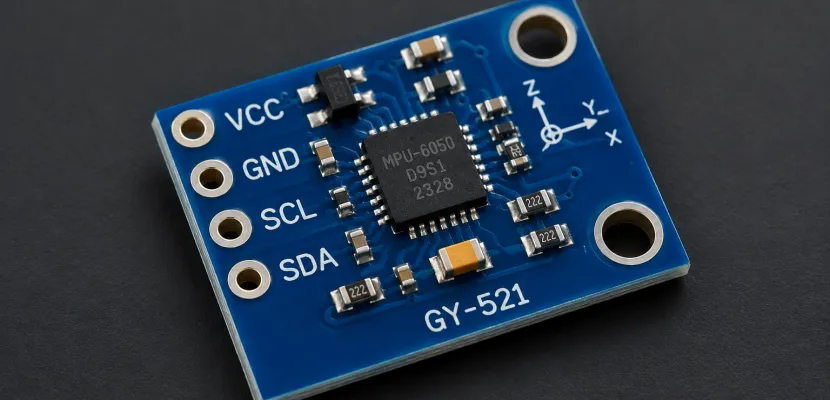
The MPU-6050 is a 6-axis motion sensor: a 3-axis accelerometer and a 3-axis gyroscope on one chip, read over I2C. It still sells in huge numbers on cheap GY-521 boards, but TDK InvenSense now lists it as end of life (EOL). This guide explains what EOL means for you, where to buy a board and what it costs, how to wire it to an Arduino, ESP32 or Raspberry Pi Pico, and how to turn its raw numbers into a steady tilt angle you can send to p5.js.
If you only need the wiring, skip to section 7. It has one pin table covering all three boards.
Key takeaways
- The MPU-6050 is EOL at TDK, and the ICM-42670-P is a current TDK 6-axis part worth considering instead. The two chips are not drop-in compatible.
- A GY-521 costs about $5 to $6.50 per board in multi-packs. The Adafruit 3886 costs $12.95.
- Read register 0x75 (WHO_AM_I) before you debug anything. 0x68 means a real MPU-6050 die. Any other value means a different chip.
- Use ±2 g and ±250 °/s for slow tilt, and average the gyro at rest to remove bias. A complementary filter then gives you stable pitch and roll.
- Yaw always drifts on a 6-axis IMU. For learning, art and prototypes the MPU-6050 is still fine. For a product, choose a current part.
Contents
- The MPU-6050 in 30 seconds, and whether to buy one in 2026
- Specs that actually matter, plus the datasheet and register map
- How it senses motion, including axis orientation
- Boards you’ll actually buy: GY-521 vs Adafruit STEMMA QT
- Where to buy an MPU-6050 in the US, and what it costs
- Is your chip real? The 60-second WHO_AM_I check
- Wiring the MPU-6050 to Arduino, ESP32 and Raspberry Pi Pico
- First readings with the Adafruit_MPU6050 library
- From raw numbers to real units
- Calibration
- Stable tilt angles: the complementary filter
- Why yaw drifts
- Streaming MPU-6050 data into p5.js and Processing
- Troubleshooting
- MPU-6050 alternatives in 2026
- FAQ
- Try it live
Fact-checked
We checked these key facts against the sources named, on November 15, 2026:
- Many GY-521 boards sold as MPU-6050 return something else (source: forum.arduino.cc)
- The chip’s core documentation hasn’t changed in more than 13 years (source: courses.cs.washington.edu)
- The Adafruit 3886 costs $12.95 for one board at Adafruit and DigiKey (source: adafruit.com)
- TDK’s MPU-6050 product page marks the chip EOL and names the ICM-42670-P as the recommended replacement (source: static.datasheets.com)
- Cheap multi-packs may carry an MPU-6500 or an unidentified clone die, even when the listing says MPU-6050 (source: eevblog.com)
The MPU-6050 in 30 seconds, and whether to buy one in 2026
The MPU-6050 measures acceleration (gravity included) and rotation rate, each on three axes. It also has a temperature sensor and an on-chip Digital Motion Processor (DMP). It still works well for tilt controllers, gesture input and interactive installations. It is the wrong choice for anything you plan to manufacture in volume.
What MPU stands for
InvenSense, now owned by TDK, called the part a MotionTracking device. Most people expand MPU as Motion Processing Unit. The DMP is the “processing” part: a small engine on the chip that can run sensor fusion so your microcontroller doesn’t have to. IMU (inertial measurement unit) is the general category, and the MPU-6050 is a 6-axis IMU.
Is the MPU-6050 obsolete?
Yes. TDK’s MPU-6050 product page marks the chip EOL and names the ICM-42670-P as the recommended replacement. One datasheet listing gives its status as obsolete, names the same alternate part and adds that “interchangeability is not guaranteed.” Distributors say the same. Octopart shows the lifecycle as “Production (not recommended for new design)”, and DigiKey listings mark the chip obsolete or no longer manufactured.
Your GY-521 board will keep working. The change is in supply, which now comes mostly from old stock and clone chips. That is why the WHO_AM_I check later in this guide matters.
Did you know?
The latest revision of the MPU-6000/MPU-6050 Product Specification is Rev 3.4, dated August 19, 2013, according to the datasheet archive on RadioLocman. The chip’s core documentation hasn’t changed in more than 13 years.
Who should use it and who shouldn’t
The MPU-6050 suits you if you are learning I2C and sensor fusion, building a gallery piece, a wearable prototype or a tilt controller, or already have a drawer of GY-521 boards. The libraries are mature and tutorials are easy to find.
Skip it if you need absolute heading (compass direction), guaranteed long-term supply, or a design you will manufacture. There is a fair counter-argument for beginners too. A newer board such as a BNO055 breakout costs more, but it gives you finished orientation output and saves you the filtering work.
Specs that actually matter (datasheet Rev 3.4)
Every number in this section comes from the MPU-6000/MPU-6050 Product Specification Rev 3.4. The settings that change your results are the full-scale ranges and their sensitivity scale factors. Both sensors use 16-bit ADCs, so a smaller range gives finer resolution.
| Setting (FS_SEL / AFS_SEL) | Gyro range (°/s) | Gyro LSB per °/s | Accel range (g) | Accel LSB per g |
|---|---|---|---|---|
| 0 | ±250 | 131 | ±2 | 16,384 |
| 1 | ±500 | 65.5 | ±4 | 8,192 |
| 2 | ±1000 | 32.8 | ±8 | 4,096 |
| 3 | ±2000 | 16.4 | ±16 | 2,048 |
| Spec | MPU-6050 value |
|---|---|
| Axes | 3-axis gyroscope + 3-axis accelerometer |
| ADC resolution | 16-bit per axis |
| Interface | I2C only, up to 400 kHz |
| I2C address | 0x68 (AD0 low) or 0x69 (AD0 high) |
| Supply (VDD) | 2.375 to 3.46 V |
| Logic supply (VLOGIC) | 1.71 V to VDD |
| Package | 4 x 4 x 0.9 mm QFN |
| Extras | DMP, 1024-byte FIFO, temperature sensor, auxiliary I2C master |
| Shock tolerance | 10,000 g |
Accelerometer ranges and LSB/g
At ±2 g, one LSB is 1/16,384 g, or about 0.06 mg. That is enough resolution to detect a sculpture leaning slightly. Switch to ±16 g only for impacts, jumps or drumstick hits, which would clip at ±2 g.
Gyroscope ranges and LSB/(°/s)
At ±250 °/s the gyro gives 131 counts per degree per second. A hand turned quickly can exceed 250 °/s, so a dancer’s wrist or a spun object needs ±1000 or ±2000 °/s. If your gyro keeps returning the same number during fast moves, it is clipping.
MPU-6050 vs MPU-6000
The two chips share a die design and a datasheet. The MPU-6000 adds an SPI interface. The MPU-6050 is I2C only and uses that pin for VLOGIC instead, so its I2C logic can run at a lower voltage than the core. Almost every hobby breakout uses the MPU-6050.
MPU-6050 datasheet and register map
The chip has two official documents, and you will need both. The first is the MPU-6000 and MPU-6050 Product Specification, Revision 3.4: 52 pages released August 19, 2013, covering electrical specs, ranges, pinout and the axis diagram. The second is the MPU-6000 and MPU-6050 Register Map and Descriptions, Revision 4.2 (document RM-MPU-6000A-00), dated August 19, 2013. Every register address in this guide comes from the register map, along with the temperature formula used later (raw / 340 + 36.53).
Earlier revisions are still around: Product Specification 3.2 (2011) and 3.3 (2012), and Register Map 4.0 (March 9, 2012). Make sure your copy says 3.4 and 4.2 respectively. Many copies online are third-party mirrors, and some are older versions.
These are the registers this guide uses:
| Register | Address | What it does | Value this guide uses |
|---|---|---|---|
| CONFIG | 0x1A | Digital low-pass filter (DLPF_CFG, bits 2:0) | Set by setFilterBandwidth() |
| GYRO_CONFIG | 0x1B | Gyro full-scale range (FS_SEL, bits 4:3) | 0 = ±250 °/s |
| ACCEL_CONFIG | 0x1C | Accel full-scale range (AFS_SEL, bits 4:3) | 0 = ±2 g |
| ACCEL_XOUT_H | 0x3B | Start of the 14-byte data block (accel, temp, gyro) | Burst read |
| TEMP_OUT_H | 0x41 | Temperature, high byte | raw / 340 + 36.53 = °C |
| GYRO_XOUT_H | 0x43 | Start of the gyro data | Inside the same burst |
| PWR_MGMT_1 | 0x6B | Sleep bit and clock source | Write 0x00 to wake |
| WHO_AM_I | 0x75 | Fixed chip ID | 0x68 on a genuine MPU-6050 |
How it senses motion (and the piezo myth)
Both sensors are MEMS structures: tiny silicon masses on springs, etched into the chip, that detect motion as changes in capacitance. Some popular tutorials say the MPU-6050 uses the piezoelectric effect. The datasheet describes capacitive sensing, so those tutorials are wrong.
Accelerometer: reading gravity for tilt
Acceleration along an axis moves that axis’s proof mass, and capacitive sensors measure the displacement differentially. When the board is still, the accelerometer reads only gravity: about +1 g on whichever axis points straight up. That makes it a tilt sensor, because the way 1 g divides across X, Y and Z gives you the board’s angle. Shake it, though, and the extra acceleration corrupts that angle.
Which way the axes point
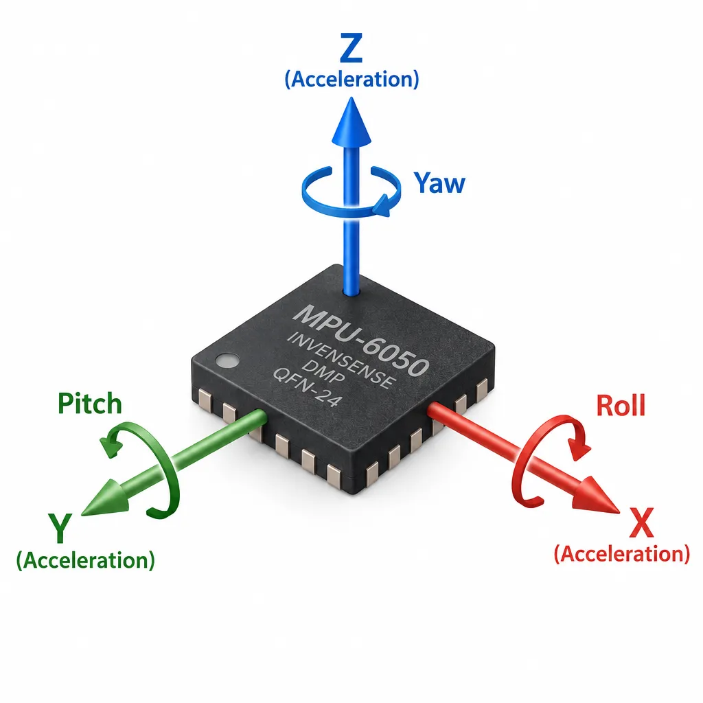
To find the axes, lay the board flat with the chip’s pin-1 dot at top left. +X runs left to right, +Y runs from front to back (away from you), and +Z points straight up out of the chip’s top face. This is the orientation diagram in the Product Specification. A SunFounder GY-521 guide gives the same rule of thumb: label up, dot at top left. Many GY-521 boards also print X and Y arrows near the chip. Board makers mount the chip in different ways, so trust a quick hand test more than the silkscreen.
             +Y  (away from you)
              ^
              |
      +---------------+
      | o             |    o = pin-1 dot on the chip
      |    MPU-6050   |
      |               | ----> +X  (to the right)
      +---------------+

      +Z points up, out of the chip's top face
      Lying flat: Z reads about +1 g (9.8 m/s^2), X and Y near 0
To test it, lower the right edge (+X) toward the table and X goes negative. Lower the far edge (+Y) and Y goes negative. A positive reading means that axis is tilted upward.
The filter code later in this guide uses this convention:
| Angle | Rotates around | Accel formula in the code | Gyro channel used |
|---|---|---|---|
| Roll | X axis | atan2(ay, az) |
g.gyro.x |
| Pitch | Y axis | atan2(-ax, sqrt(ay*ay + az*az)) |
g.gyro.y |
| Yaw | Z axis | none (gravity can’t see it) | g.gyro.z, uncorrected |
If you mount the board on its edge or upside down, swap or negate axes in code to match. Don’t rewrite the filter.
Gyroscope: rotation rate, not angle
The gyro contains three vibrating masses. When the chip rotates, the Coriolis effect pushes each vibration sideways, and a capacitive pickoff measures that push. The output is angular velocity in °/s. To get an angle you have to integrate over time, and every small error gets integrated along with the signal. That is the source of drift.
Boards you’ll actually buy: GY-521 vs Adafruit STEMMA QT
You will rarely handle the bare 4 mm chip. Most people buy a GY-521 breakout, often in multi-packs, or Adafruit’s MPU-6050 board (product 3886). The GY-521 is cheap but of unknown origin. The Adafruit board costs more, comes from a known supply chain and has documentation.
| Board | Price (November 2026) | Size | Connectors | Logic levels | Chip provenance |
|---|---|---|---|---|---|
| GY-521 (e.g. AITRIP 5-pack) | About $5.20 to $6.50 per board in 3- and 5-packs | 1.65 x 2.0 cm PCB | 8-pin 0.1″ header, you solder it | 3.3 to 5 V supply via onboard regulator | Unknown; clones common, check WHO_AM_I |
| Adafruit MPU-6050 (3886) | $12.95 (1 to 9), $11.66 (10 to 99), $10.36 (100+) | 26.0 x 17.8 x 4.6 mm, 1.8 g | 2x STEMMA QT plus header | 3 to 5 V, regulated | Adafruit-sourced; PCB silkscreen updated July 26, 2023 |
The AITRIP listing on Amazon is rated 4.2 out of 5 from 93 reviews, and 11% of those reviews are 1-star. That pattern fits a board where most units work and some arrive with a different die or bad solder joints.
GY-521 pinout explained
- VCC: power in. The onboard regulator accepts 3.3 to 5 V.
- GND: ground.
- SCL: I2C clock.
- SDA: I2C data.
- XDA: auxiliary I2C data, for an external sensor such as a magnetometer.
- XCL: auxiliary I2C clock.
- AD0: address select. Low or unconnected gives 0x68, high gives 0x69.
- INT: interrupt output, which DMP code uses to signal fresh data.
The GY-521 has pull-up resistors on SDA and SCL to its own 3.3 V rail. In practice it works with 5 V Arduino boards without a level shifter.
Adafruit 3886 board
Adafruit’s board adds two STEMMA QT sockets, which also accept SparkFun Qwiic cables, so you can chain it to other I2C sensors without soldering. The cable is sold separately. The board works with the Adafruit_MPU6050 Arduino library and the Adafruit CircuitPython MPU6050 library. Adafruit’s own store page calls the chip “an oldie but goodie.”
Where to buy an MPU-6050 in the US (and what it costs)
In November 2026, GY-521 boards cost about $5 to $6.50 each in multi-packs from marketplace sellers. The Adafruit 3886 costs $12.95 for one board at Adafruit and DigiKey. Marketplace prices change week to week, so the figures below are snapshots from listings in November 2026, not fixed prices.
| Where | Board | Listed price (November 2026) | Per board | Notes |
|---|---|---|---|---|
| Adafruit | MPU-6050 STEMMA QT (3886) | $12.95 (1 to 9), $11.66 (10 to 99), $10.36 (100+) | $10.36 to $12.95 | Maker’s own store; quantity tiers |
| DigiKey | Adafruit 3886 (1528-3886-ND) | $12.95 | $12.95 | Showed stock at time of listing |
| Micro Center | Adafruit 3886 (SKU 262139) | $12.99 | $12.99 | In-store pickup |
| PiShop.us | Adafruit 3886 | $15.40 | $15.40 | Listed in stock |
| eBay | AITRIP GY-521, 5-pack | $26.10, free delivery | About $5.22 | Headers included, unsoldered |
| eBay | Generic GY-521, 3-pack | $16.62 to $19.47 | About $5.54 to $6.49 | Seller and chip origin vary |
Mouser also stocks the Adafruit board as part 485-3886, and Adafruit lists Mouser, DigiKey and PiShop.us among its US distributors. On Amazon, AITRIP sells GY-521 5-packs and 10-packs, and HiLetgo sells singles and 3-packs. Several 5-pack listings from other brands showed no featured offer when checked, so availability there changes often.
Buy the GY-521 if you want several sensors for learning or experiments, can solder a header, and are willing to check each board’s WHO_AM_I. At about $5 a board, a dud is cheap to replace.
Buy the Adafruit 3886 if you want solder-free STEMMA QT or Qwiic wiring, documentation that matches the board, or a sensor for a show you can’t afford to have fail. It costs about twice as much and gives you a known part from a known supplier.
Buy neither if you need heading or a design you will manufacture. The alternatives section near the end covers those cases.
Heads up
Cheap multi-packs may carry an MPU-6500 or an unidentified clone die, even when the listing says MPU-6050. Budget for one board in a pack failing the WHO_AM_I check.
Is your chip real? The 60-second WHO_AM_I check
Register 0x75 (WHO_AM_I) holds a fixed ID, and a genuine MPU-6050 returns 0x68. Many GY-521 boards sold as MPU-6050 return something else. Read the ID before you blame your code.
Reading WHO_AM_I
This sketch scans the I2C bus, then reads the ID at whichever MPU address responds. It uses only the built-in Wire library.
\#include <Wire.h>

void setup() {
  Serial.begin(115200);
  while (!Serial) delay(10);
  Wire.begin();

  // 1. Scan the bus
  for (uint8_t addr = 1; addr < 127; addr++) {
    Wire.beginTransmission(addr);
    if (Wire.endTransmission() == 0) {
      Serial.print("Device at 0x");
      Serial.println(addr, HEX);
    }
  }

  // 2. Read WHO_AM_I at both possible MPU addresses
  uint8_t addrs[] = {0x68, 0x69};
  for (uint8_t a : addrs) {
    Wire.beginTransmission(a);
    Wire.write(0x75);                 // WHO_AM_I register
    if (Wire.endTransmission(false) != 0) continue;
    Wire.requestFrom(a, (uint8_t)1);
    if (Wire.available()) {
      Serial.print("WHO_AM_I at 0x");
      Serial.print(a, HEX);
      Serial.print(" = 0x");
      Serial.println(Wire.read(), HEX);
    }
  }
}

void loop() {}
Clone IDs and library workarounds
| Value returned | Likely chip | Works with Adafruit lib? | Action |
|---|---|---|---|
| 0x68 | MPU-6050 | Yes | Carry on |
| 0x70 | MPU-6500 | No, begin() fails | Use a library that accepts 0x70, or read registers directly |
| 0x71 | MPU-9250 (has magnetometer) | No | Use an MPU-9250 library; you also gain a compass |
| 0x98 | Unknown or clone die | No | Try direct register reads; treat specs as unverified |
| No reply | Wiring, address or dead board | n/a | Check solder joints, power and SDA/SCL |
A board that returns 0x70 or 0x98 is not necessarily broken. The basic accelerometer and gyro registers are often at the same addresses, so the raw-read code below can still work. What you lose is any guarantee that the DMP and the datasheet specs apply. Arduino Forum users have reported 0x98 boards since at least 2021.
Studio tip
Run the scanner and WHO_AM_I sketch on every board when you open a new pack of GY-521s, and write each board’s ID on masking tape. It takes two minutes and can save you an evening chasing a “Failed to find MPU6050 chip” error.
Wiring the MPU-6050 to Arduino, ESP32 and Raspberry Pi Pico
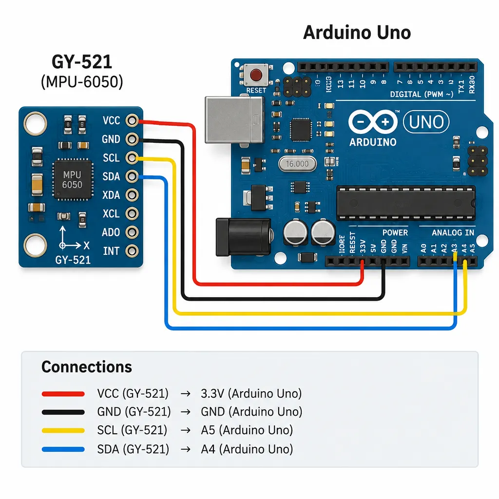
You need four wires: power, ground, SDA and SCL. AD0 and INT are optional. Leave XDA and XCL unconnected unless you add a second sensor on the auxiliary bus.
| MPU-6050 pin | Arduino Uno (R3/R4) | ESP32 (DevKit) | Raspberry Pi Pico | Notes |
|---|---|---|---|---|
| VCC | 5V or 3.3V | 3V3 | 3V3(OUT), pin 36 | GY-521 regulator takes 3.3 to 5 V |
| GND | GND | GND | GND, pin 38 | Common ground is required |
| SCL | A5 (or SCL header) | GPIO22 | GP5, pin 7 | I2C clock |
| SDA | A4 (or SDA header) | GPIO21 | GP4, pin 6 | I2C data |
| AD0 | Unconnected or GND | Unconnected or GND | Unconnected or GND | Tie to VCC for 0x69 |
| INT | D2 (optional) | Any GPIO | Any GP pin | Needed for DMP interrupt code |
Quick steps: wire and test a GY-521 on an Uno
- Solder the 8-pin header.
- Connect VCC to 5V and GND to GND.
- Connect SDA to A4 and SCL to A5.
- Upload the WHO_AM_I sketch at 115200 baud.
- Look for 0x68, then run the library example.
Arduino Uno R3 and R4
On both Uno boards, A4 and A5 also serve as SDA and SCL. The Arduino Uno R4 WiFi has a Qwiic socket that accepts the Adafruit board’s STEMMA QT cable. That socket is on the second I2C bus, so call mpu.begin(0x68, &Wire1) instead of the default.
ESP32
GPIO21 (SDA) and GPIO22 (SCL) are the usual defaults on ESP32 DevKit boards. The ESP32 can route I2C to almost any pin, so Wire.begin(sda, scl) lets you move it. Power the sensor from 3V3.
Raspberry Pi Pico and Raspberry Pi (CircuitPython/Python)
On a Pico running CircuitPython, install the Adafruit CircuitPython MPU6050 library and create the I2C bus yourself:
import time
import board
import busio
import adafruit_mpu6050

i2c = busio.I2C(scl=board.GP5, sda=board.GP4)
mpu = adafruit_mpu6050.MPU6050(i2c)

while True:
    print("Accel m/s^2:", mpu.acceleration)
    print("Gyro rad/s:", mpu.gyro)
    print("Temp C:", mpu.temperature)
    time.sleep(0.1)
On a full Raspberry Pi, use physical pin 1 (3.3 V), pin 3 (SDA), pin 5 (SCL) and pin 6 (GND). Enable I2C in raspi-config, check the connection with i2cdetect -y 1, and run the same library through Adafruit Blinka.
Two MPU-6050s on one bus
Leave AD0 low on one board (0x68) and tie AD0 to VCC on the other (0x69). Then create two objects and call mpu1.begin(0x68) and mpu2.begin(0x69). The chip offers only two addresses, so three or more sensors need an I2C multiplexer such as a TCA9548A.
First readings with the Adafruit_MPU6050 library
The Adafruit_MPU6050 library is the easiest place for most people to start. Install it from the Arduino Library Manager and accept the dependencies it offers (Adafruit BusIO and Adafruit Unified Sensor). The latest release is v2.2.9, from February 11, 2026, a week after v2.2.7 and v2.2.8. It is free and BSD-licensed.
\#include <Adafruit_MPU6050.h>
\#include <Adafruit_Sensor.h>
\#include <Wire.h>

Adafruit_MPU6050 mpu;

void setup() {
  Serial.begin(115200);
  while (!Serial) delay(10);

  if (!mpu.begin()) {                       // default address 0x68
    Serial.println("Failed to find MPU6050 chip");
    while (1) delay(10);
  }

  mpu.setAccelerometerRange(MPU6050_RANGE_2_G);
  mpu.setGyroRange(MPU6050_RANGE_250_DEG);
  mpu.setFilterBandwidth(MPU6050_BAND_21_HZ);
}

void loop() {
  sensors_event_t a, g, temp;
  mpu.getEvent(&a, &g, &temp);

  // Acceleration in m/s^2, rotation in rad/s, temperature in C
  Serial.print(a.acceleration.x); Serial.print(',');
  Serial.print(a.acceleration.y); Serial.print(',');
  Serial.print(a.acceleration.z); Serial.print(',');
  Serial.print(g.gyro.x);         Serial.print(',');
  Serial.print(g.gyro.y);         Serial.print(',');
  Serial.print(g.gyro.z);         Serial.print(',');
  Serial.println(temp.temperature);
  delay(20);
}
With the board lying flat, Z should read about 9.8 m/s² and X and Y should be near zero. Open the Serial Plotter to watch the curves change as you tilt it.
Picking the right range for your project
Choose the smallest range your motion never exceeds.
| Project | Accel range | Gyro range |
|---|---|---|
| Slow tilt, plinths, balance boards | MPU6050_RANGE_2_G |
MPU6050_RANGE_250_DEG |
| Handheld controllers and wands | MPU6050_RANGE_4_G |
MPU6050_RANGE_500_DEG |
| Wearables on dancers, thrown or spun objects | MPU6050_RANGE_8_G or MPU6050_RANGE_16_G |
MPU6050_RANGE_1000_DEG or MPU6050_RANGE_2000_DEG |
Digital low-pass filter settings
setFilterBandwidth() sets the chip’s built-in digital low-pass filter, which lives in the CONFIG register (0x1A). The options are MPU6050_BAND_260_HZ, 184, 94, 44, 21, 10 and 5_HZ. Lower bandwidth gives smoother values with more lag. About 21 Hz suits tilt-driven visuals. For tap or hit detection, use 94 Hz or higher so short spikes get through.
From raw numbers to real units
Whether you use a library or read registers directly, the chip gives you signed 16-bit counts. Divide by the scale factor for your range to get g or °/s. Once you know how, you aren’t tied to one library, which helps with 0x70 and 0x98 boards.
\#include <Wire.h>
const uint8_t MPU = 0x68;

void setup() {
  Serial.begin(115200);
  Wire.begin();
  Wire.beginTransmission(MPU);
  Wire.write(0x6B);   // PWR_MGMT_1
  Wire.write(0x00);   // wake the chip from sleep
  Wire.endTransmission();
}

int16_t read16() { return (Wire.read() << 8) | Wire.read(); }

void loop() {
  Wire.beginTransmission(MPU);
  Wire.write(0x3B);                 // ACCEL_XOUT_H, start of data block
  Wire.endTransmission(false);
  Wire.requestFrom(MPU, (uint8_t)14);
  int16_t ax = read16(), ay = read16(), az = read16();
  int16_t t  = read16();
  int16_t gx = read16(), gy = read16(), gz = read16();

  // Default ranges after reset: +/-2 g and +/-250 deg/s
  Serial.print(ax / 16384.0); Serial.print(',');
  Serial.print(ay / 16384.0); Serial.print(',');
  Serial.print(az / 16384.0); Serial.print(',');
  Serial.print(gx / 131.0);   Serial.print(',');
  Serial.print(gy / 131.0);   Serial.print(',');
  Serial.print(gz / 131.0);   Serial.print(',');
  Serial.println(t / 340.0 + 36.53);  // temperature in C
  delay(20);
}
Raw to g
At ±2 g, a raw reading of 8,192 is 8,192 / 16,384 = 0.5 g. That means the axis is tilted about 30° above horizontal, because sin(30°) = 0.5. A positive reading means the axis points up. At ±8 g, the same 0.5 g reads 2,048 counts.
Raw to °/s
At ±250 °/s, a raw gyro value of −3,275 is −3,275 / 131 = −25.0 °/s. At ±2000 °/s the same rotation reads about −410 counts. You lose resolution and gain headroom.
Calibration: zeroing offsets in 2 minutes
Every MPU-6050 has a gyro bias: at rest it reports a small nonzero rotation, and integrating that bias produces drift. To fix it, keep the sensor still at startup, average a few hundred gyro samples, and subtract that average from every later reading.
- Place the board flat and motionless.
- Average 500 gyro samples per axis. With a 3 ms delay that takes about 2 seconds.
- Save the averages as
gxBias,gyBias,gzBiasand subtract them inloop(). - For accelerometer offsets, average X and Y with the board flat (both should read 0). Then average Z and subtract 9.81 m/s².
- Store the values in EEPROM on an Uno, or with the Preferences library on an ESP32, so a permanent installation can skip calibration.
The complementary filter sketch in the next section includes the gyro routine. The i2cdevlib MPU6050 library also includes an IMU_Zero example that calculates values for the chip’s own offset registers.
Studio tip
In an installation, power up the sensor before visitors can touch it, and run the gyro average then. If a plinth boots while someone is leaning on it, it will treat that person’s tilt as level.
Stable tilt angles: the complementary filter
A complementary filter blends the gyro’s smooth short-term angle with the accelerometer’s drift-free long-term angle. It needs one line of maths per axis and runs easily on an Arduino Uno. For pitch and roll, start here.
Why accel alone jitters and gyro alone drifts
The accelerometer angle is right on average, but every bump and vibration shows up in it. The integrated gyro angle is smooth, but its error keeps growing. If you trust the gyro over short timescales and let the accelerometer slowly pull the result back, you get the strengths of both.
Complementary filter code
\#include <Adafruit_MPU6050.h>
\#include <Adafruit_Sensor.h>
\#include <Wire.h>

Adafruit_MPU6050 mpu;
float gxBias = 0, gyBias = 0;
float pitch = 0, roll = 0;
const float ALPHA = 0.98;          // gyro weight, 0.9 to 0.995
unsigned long lastMicros;

void calibrateGyro(int n) {
  sensors_event_t a, g, t;
  for (int i = 0; i < n; i++) {
    mpu.getEvent(&a, &g, &t);
    gxBias += g.gyro.x;
    gyBias += g.gyro.y;
    delay(3);
  }
  gxBias /= n;
  gyBias /= n;
}

void accelAngles(sensors_event_t &a, float &p, float &r) {
  float ax = a.acceleration.x, ay = a.acceleration.y, az = a.acceleration.z;
  r = atan2(ay, az) * RAD_TO_DEG;
  p = atan2(-ax, sqrt(ay * ay + az * az)) * RAD_TO_DEG;
}

void setup() {
  Serial.begin(115200);
  if (!mpu.begin()) {
    Serial.println("Failed to find MPU6050 chip");
    while (1) delay(10);
  }
  mpu.setAccelerometerRange(MPU6050_RANGE_2_G);
  mpu.setGyroRange(MPU6050_RANGE_250_DEG);
  mpu.setFilterBandwidth(MPU6050_BAND_21_HZ);
  delay(100);
  calibrateGyro(500);              // keep the sensor still

  sensors_event_t a, g, t;
  mpu.getEvent(&a, &g, &t);
  accelAngles(a, pitch, roll);     // start from the accel angle
  lastMicros = micros();
}

void loop() {
  sensors_event_t a, g, t;
  mpu.getEvent(&a, &g, &t);

  unsigned long now = micros();
  float dt = (now - lastMicros) / 1000000.0;
  lastMicros = now;

  float accPitch, accRoll;
  accelAngles(a, accPitch, accRoll);
  float rollRate  = (g.gyro.x - gxBias) * RAD_TO_DEG;   // deg/s
  float pitchRate = (g.gyro.y - gyBias) * RAD_TO_DEG;

  roll  = ALPHA * (roll  + rollRate  * dt) + (1 - ALPHA) * accRoll;
  pitch = ALPHA * (pitch + pitchRate * dt) + (1 - ALPHA) * accPitch;

  // One line per sample: pitch,roll
  Serial.print(pitch, 2);
  Serial.print(',');
  Serial.println(roll, 2);
  delay(10);
}
Roll here is rotation around the X axis and pitch is rotation around the Y axis, matching the axis table in the accelerometer section. To tune alpha, use the time constant τ = α·dt / (1 − α). With α = 0.98 and a 10 ms loop, τ is about 0.49 s, so the accelerometer pulls the angle back over roughly half a second. Raise alpha toward 0.995 if vibration makes the angle shake. Lower it toward 0.95 if the angle creeps after fast moves.
When to use the DMP instead
The DMP fuses the sensor data on the chip and outputs a quaternion. That avoids the gimbal problems the atan2 formulas have near ±90° pitch. The usual route is Jeff Rowberg’s i2cdevlib MPU6050 library and its MPU6050_DMP6 example, which uses the INT pin. The Library Manager also offers an Electronic Cats fork of the library. Use the DMP when your piece flips or rolls all the way over. Use the complementary filter when you want code you can read and change.
Why yaw drifts, and what to do about it
Yaw (rotation around the vertical Z axis) drifts on every MPU-6050 because nothing on the chip senses heading. Gravity corrects pitch and roll, but gravity looks the same whichever way the board faces, so gyro Z is integrated with no correction at all. This explains the common forum complaint that the gyro’s Z axis keeps drifting.
The error adds up quickly. In a measurement by Kris Winer, published in a Parallax document, a GY-521 without a magnetometer drifted about 1.8° per minute. Over a four-hour gallery shift, an uncorrected heading could wander 432°, more than a full turn.
There are three realistic fixes:
- Add a magnetometer on XDA/XCL or the main bus, and fuse its readings. This works, but nearby motors, speakers and steel will distort it.
- Upgrade to a 9-axis part with on-chip fusion, such as the Bosch BNO055, which outputs absolute orientation directly.
- Design around relative rotation. Use yaw rate (how fast something turns) instead of heading (which way it faces), or re-zero yaw whenever the object is at rest.
Studio tip
For performers and wearables, build the piece around pitch, roll and short gestures. A flick, a lean or a spin rate stays reliable for hours, but “which way is the dancer facing” does not.
Make it move: streaming MPU-6050 data into p5.js and Processing
The filter sketch already sends what a creative tool needs: one pitch,roll line per sample at 115200 baud. In a browser, p5.js reads it through the Web Serial API. Processing reads it with its built-in Serial library. Both tools are free. If you haven’t used p5.js, it brings Processing’s sketchbook approach to JavaScript and runs in any browser. The exception is serial access: Web Serial works only in Chrome and Edge.
Serial format that won’t break
- Send one sample per line, ending in a newline (
Serial.println). - Send plain numbers separated by commas, with no labels or units.
- Keep the number of fields fixed, so the receiver can drop any line that doesn’t match.
- Close the Arduino Serial Monitor before you connect from p5.js or Processing, because only one program can hold the port.
p5.js Web Serial sketch
The full p5.js sketch is in the “Try it live” section at the end. Press C and choose your Arduino’s port, and the virtual board tilts with the real one. Without a sensor, the mouse stands in for the data.
Processing alternative
import processing.serial.*;

Serial port;
float pitch, roll;

void setup() {
  size(800, 600, P3D);
  printArray(Serial.list());              // find your port index
  port = new Serial(this, Serial.list()[0], 115200);
  port.bufferUntil('\n');
}

void serialEvent(Serial p) {
  String s = p.readString();
  if (s == null) return;
  float[] v = float(split(trim(s), ','));
  if (v.length == 2 && !Float.isNaN(v[0]) && !Float.isNaN(v[1])) {
    pitch = v[0];
    roll = v[1];
  }
}

void draw() {
  background(15);
  lights();
  translate(width / 2, height / 2);
  rotateX(radians(pitch));
  rotateZ(radians(roll));
  fill(30, 120, 90);
  box(320, 16, 200);
}
Smoothing for installations (lerp, dead zones)
Even filtered data trembles by a fraction of a degree, and visitors read that tremble as nervousness. Two fixes work well. Ease toward each new value with lerp(current, target, 0.1). And ignore changes smaller than about a degree (a dead zone), so an object at rest looks completely still. The same tricks help with analog joysticks in custom controllers. For more organic movement while a piece sits idle, blend in a small amount of Perlin noise.
Heads up
Web Serial needs a user gesture (a click or key press) to open a port, and it doesn’t work in Firefox or Safari. For gallery shows, plan on a kiosk machine running Chrome or Edge.
Troubleshooting
Most MPU-6050 problems come from wiring, the I2C address or the chip ID, not from code. Work through the table in order.
| Symptom | Likely cause | Fix |
|---|---|---|
| “Failed to find MPU6050 chip” | Wrong wiring, wrong address, or WHO_AM_I not 0x68 | Run the scanner; try mpu.begin(0x69); read WHO_AM_I |
| Scanner finds nothing | SDA/SCL swapped, no common ground, unsoldered header | Swap the two lines; reflow the header pins |
| All values zero | Chip still asleep (raw reads) | Write 0x00 to register 0x6B first |
| Values freeze or the I2C bus hangs | Long wires, loose joints, noise from motors | Keep wires under about 30 cm, twist SDA/SCL with GND, add a timeout with Wire.setWireTimeout() on AVR |
| Readings stuck at ±32767 | Range too small for the motion | Raise the gyro or accel range |
| Gyro drifts badly only on fast moves | Gyro clipping at ±250 °/s, or a slow loop with inaccurate dt | Use ±1000 °/s; measure dt with micros() |
| Axis direction looks reversed | Board mounted in a different orientation | Check against the axis diagram, flip the sign or swap axes in code, then test each axis by hand |
| Works on 3.3 V, fails on 5 V (or the reverse) | Bare-chip board without a regulator | Check the board; the chip itself needs 2.375 to 3.46 V |
Cold solder joints on GY-521 header pins cause many of these failures. A joint can look fine and still lose contact when the cable moves. If values cut out only when you touch the wires, reflow all eight pins.
MPU-6050 alternatives in 2026
The best replacement depends on what you need: a current part for a product, finished orientation output, or better raw performance. The chips below are compared on lifecycle status, whether they compute orientation themselves, and how easy they are to find on maker-friendly breakouts. That last factor counts heavily for artists, who rarely design their own PCBs.
| Chip | Maker | Axes | On-chip orientation | Best for |
|---|---|---|---|---|
| MPU-6050 | TDK InvenSense | 6 | DMP (quaternion) | Learning, prototypes, existing stock |
| ICM-42670-P | TDK InvenSense | 6 | No | New designs that need TDK’s official successor |
| BNO055 | Bosch | 9 | Yes, absolute orientation | Installations that need real heading |
| LSM6DSOX | STMicroelectronics | 6 | No (has a machine learning core) | Gesture detection, low-power wearables |
| ISM330DHCX | STMicroelectronics | 6 | No | Industrial-grade temperature range and stability |
| BMI270 | Bosch | 6 | No | Wearables, low-power motion |
ICM-42670-P (official replacement)
TDK recommends the ICM-42670-P, but it is a different chip, not a reissue. It comes in a 2.5 x 3 mm 14-pin LGA package (the MPU-6050 is a 4 x 4 mm QFN), runs from 1.71 to 3.6 V and is rated for −40 to +85 °C. Its register map is different, so you need a new library. The listing that names it as the alternate says plainly that interchangeability is not guaranteed, and one distributor shows a 26-week standard lead time. Forum users often ask whether it is “totally pin compatible and software compatible.” It is neither.
Did you know?
The MPU-6050 datasheet listing on Datasheets.com names the ICM-42670-P as the recommended alternate and, in the same entry, warns “Interchangeability is not guaranteed.” Even TDK’s own successor is a redesign, not a swap.
BNO055 (on-chip orientation)
If yaw drift is your problem, the BNO055 solves it. It fuses its accelerometer, gyro and magnetometer readings on the chip and reports Euler angles or quaternions. You give up the hands-on filter work, and your sketch gets orientation it can use right away. Adafruit sells it on a STEMMA QT breakout.
LSM6DSOX, ISM330DHCX and BMI270
These are current 6-axis parts from STMicroelectronics and Bosch. Like the MPU-6050, none of them has a heading reference. Choose one when you want a supported chip with modern features: low power, built-in gesture detection or a wider industrial temperature range. The same reasoning answers “MPU-6050 or ICM-20948?” The ICM-20948 is a 9-axis TDK part with a magnetometer, so choose it only if you need heading.
FAQ
What does the MPU6050 sensor do?
It measures acceleration (gravity included) and rotation rate, each on three axes, plus temperature. From those readings you can calculate tilt, detect gestures and taps, and estimate orientation.
Is the MPU6050 obsolete?
Yes. TDK InvenSense lists it as EOL and recommends the ICM-42670-P. Distributors mark it obsolete or not recommended for new designs. Existing boards still work fine for learning and art projects.
How much does an MPU-6050 cost?
In November 2026, GY-521 boards cost about $5.20 to $6.50 each in 3- and 5-packs from marketplace sellers. The Adafruit 3886 costs $12.95 for one, dropping to $11.66 for 10 to 99 and $10.36 for 100 or more. PiShop.us lists it at $15.40.
How do I connect the MPU6050 sensor to my Arduino?
On an Uno, connect VCC to 5V (or 3.3V), GND to GND, SDA to A4 and SCL to A5. Install the Adafruit_MPU6050 library and run its example at 115200 baud. You should see readings.
Which way do the MPU-6050 axes point?
Lay the board flat with the chip’s pin-1 dot at top left. +X points right, +Y points away from you and +Z points up. Lying flat, Z reads about +9.8 m/s².
Where can I find the MPU-6050 datasheet and register map?
There are two documents: the MPU-6000 and MPU-6050 Product Specification, Revision 3.4, and the MPU-6000 and MPU-6050 Register Map and Descriptions, Revision 4.2. Both were released August 19, 2013. The register map lists every address, including 0x6B, 0x3B and 0x75.
What does MPU stand for in MPU6050?
MPU is InvenSense’s product prefix for its MotionTracking devices, usually expanded as Motion Processing Unit. The name refers to the on-chip Digital Motion Processor.
What is the difference between the GY-521 and the MPU-6050?
The MPU-6050 is the chip. The GY-521 is a cheap breakout board that carries the chip (or a clone), adds a 3.3 V regulator and pull-up resistors, and brings out eight header pins.
Is the MPU-6050 3.3V or 5V?
The chip runs on 2.375 to 3.46 V. GY-521 and Adafruit boards add a regulator, so you can power them from 3.3 V or 5 V. Never connect 5 V directly to a bare chip.
What is the I2C address of the MPU-6050?
The address is 0x68 when AD0 is low or unconnected and 0x69 when AD0 is tied high. Using both lets you put two sensors on one bus.
Which MPU-6050 library should I use?
Start with Adafruit_MPU6050 (v2.2.9) for clean SI units and easy range settings. Switch to i2cdevlib when you need the DMP’s quaternion output. On a Pico or Raspberry Pi, use Adafruit CircuitPython MPU6050.
Why does my MPU-6050 yaw keep drifting?
A 6-axis IMU has nothing that senses heading, so error in the integrated gyro Z reading is never corrected. Subtracting the gyro bias slows the drift. Only a magnetometer or a 9-axis part such as the BNO055 removes it.
WHO_AM_I returns 0x70 on my GY-521. Is it broken?
No. 0x70 is the MPU-6500’s ID, so your board carries a different chip. The Adafruit library rejects it, but raw register reads or an MPU-6500-aware library usually work.
What is the best replacement for the MPU-6050?
For a new product design, use TDK’s ICM-42670-P, knowing it needs new code and a new layout. For an art installation that needs a steady heading, a BNO055 breakout is the more practical swap.
Try it live
This sketch draws a virtual MPU-6050 board that tilts along with your sensor. Load the complementary filter sketch onto your Arduino and close the Serial Monitor. Then click the canvas, press C and choose the port. Without hardware, the mouse fakes the tilt so you can still try it.
// MPU-6050 tilt viewer for p5.js 1.x
// Arduino sends lines like "12.40,-3.15" (pitch,roll) at 115200 baud.
// Press C to connect over Web Serial (Chrome or Edge only).
// Without a sensor, move the mouse to fake the tilt.

let pitch = 0;          // smoothed pitch in degrees
let roll = 0;           // smoothed roll in degrees
let targetPitch = 0;    // newest value from sensor or mouse
let targetRoll = 0;
let connected = false;  // true once a port is open
let buffer = '';        // holds partial lines between reads
let message = 'Move the mouse, or click and press C to connect a sensor';
let hud;                // flat 2D layer for the text
const DEAD_ZONE = 0.8;  // ignore changes smaller than this (degrees)

function setup() {
  createCanvas(800, 600, WEBGL);
  hud = createGraphics(800, 40);
}

function draw() {
  background(12, 14, 20);

  // With no sensor, the mouse stands in for tilt
  if (!connected) {
    targetRoll = map(mouseX, 0, width, -60, 60, true);
    targetPitch = map(mouseY, 0, height, -60, 60, true);
  }

  // Ease toward the target so motion feels calm
  pitch = lerp(pitch, targetPitch, 0.12);
  roll = lerp(roll, targetRoll, 0.12);

  ambientLight(70);
  directionalLight(255, 255, 255, 0.3, 0.6, -1);

  // The breakout board
  push();
  rotateX(radians(pitch));
  rotateZ(radians(roll));
  ambientMaterial(30, 120, 90);   // PCB green
  box(320, 16, 200);
  translate(0, -12, 0);           // the chip sits on top
  ambientMaterial(25);
  box(60, 8, 60);
  pop();

  // A ball on a floor that rolls downhill with the tilt
  push();
  translate(0, 200, 0);
  ambientMaterial(40, 44, 60);
  box(640, 4, 360);
  let bx = constrain(roll * 4, -300, 300);
  let bz = constrain(-pitch * 3, -160, 160);
  let heat = constrain(abs(pitch) + abs(roll), 0, 90);
  translate(bx, -24, bz);
  ambientMaterial(map(heat, 0, 90, 80, 255), 140, map(heat, 0, 90, 255, 60));
  sphere(20);
  pop();

  // Text overlay, drawn flat on top
  noLights();
  hud.clear();
  hud.fill(230);
  hud.textSize(16);
  let info = connected
    ? 'Live  pitch ' + nf(pitch, 1, 1) + '   roll ' + nf(roll, 1, 1)
    : message;
  hud.text(info, 16, 26);
  image(hud, -width / 2, -height / 2);
}

function keyPressed() {
  if ((key === 'c' || key === 'C') && !connected) {
    if ('serial' in navigator) {
      connectSerial();
    } else {
      message = 'Web Serial is not available here. Try Chrome or Edge.';
    }
  }
}

async function connectSerial() {
  try {
    const port = await navigator.serial.requestPort();
    await port.open({ baudRate: 115200 });
    connected = true;
    const decoder = new TextDecoderStream();
    port.readable.pipeTo(decoder.writable);
    const reader = decoder.readable.getReader();
    while (true) {
      const { value, done } = await reader.read();
      if (done) break;
      buffer += value;
      const lines = buffer.split('\n');
      buffer = lines.pop();          // keep the unfinished line
      for (const line of lines) parseLine(line);
    }
  } catch (err) {
    connected = false;
    message = 'Could not open the port. Close the Serial Monitor and try again.';
  }
}

// Turn "pitch,roll" into numbers, skipping anything malformed
function parseLine(line) {
  const parts = line.trim().split(',');
  if (parts.length !== 2) return;
  const p = parseFloat(parts[0]);
  const r = parseFloat(parts[1]);
  if (isNaN(p) || isNaN(r)) return;
  if (abs(p - targetPitch) > DEAD_ZONE) targetPitch = p;
  if (abs(r - targetRoll) > DEAD_ZONE) targetRoll = r;
}
Once the board tilts on screen, replace the shapes with whatever your piece needs: a particle field, a sound parameter, a camera angle. As long as each serial line holds two plain numbers, the rest of the pipeline stays the same. Good next projects are a balance-board installation and a tilt-controlled sculpture.
On this article
- Facts were checked against the sources below before publication.
- Published
Sources (8)
- MPU-6050 Six-Axis (Gyro + Accelerometer) - TDK InvenSense (adm.invensense.tdk.com)
- TDK MPU-6050 datasheet listing (datasheets.com)
- InvenSense MPU-6050 - Octopart (octopart.com)
- MPU-6000/MPU-6050 Product Specification Rev 3.4 (alliance.seas.upenn.edu)
- MPU6050 Datasheet Explained - Ultra Librarian (ultralibrarian.com)
- MPU-6050 datasheet revisions - RadioLocman (radiolocman.com)
- Adafruit MPU6050 - Arduino Libraries (arduinolibraries.info)
- Adafruit MPU-6050 6-DoF Accel and Gyro Sensor - STEMMA QT Qwiic (adafruit.com)